


Splicing procedure, step by step
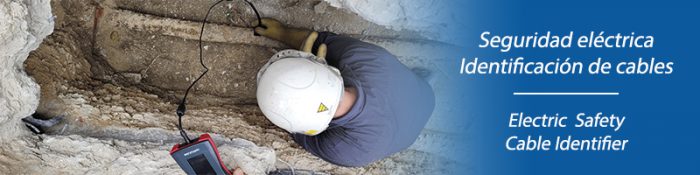
Introduction
Electrical cable jointing is the procedure by which two or more electrical conductors are joined together to guarantee the continuity of the circuit, with a safe and efficient connection. It is necessary to ensure good electrical contact, avoiding faults such as overheating, sparking or loss of energy. And always complying with electrical safety regulations, thus guaranteeing the safety of the operators who handle the cables, the installation and the population in general.
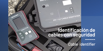
During maintenance work on low and medium voltage electrical networks, it is common to cut and reconnect electrical cables. This task may be necessary due to the replacement of a deteriorated cable section, the repair of an existing line or the creation of a new branch. The correct identification of the line and its phases to be handled is of vital importance. In this article we explain the steps to follow in order to carry out the tapping always with total safety with the Merytronic PI-3 feeder and 3-phase identifier.
In order to optimise operating times, it is recommended to use 2 identification devices, with different coding, A and B.

Initial situation
A feeder between two Secondary Substations SS1 and SS2 located several kilometres apart is to be connected.

Request for discharge
Discharge is requested in both SS1 and SS2, meaning the cell switches are opened, the feeder is short-circuited at both ends, and grounded.
Phase matching check
As the phases R, S and T are not known at substation level, an initial phase matching test is carried out. To do this, a signal is injected with TR-A at the source and the feeder is identified (and the phases are marked) at SS2, and at the junction.
Step 1. The transmitter of devicet A is placed at SS1 (source): TR-A.
- Mark phase 1 and place clamp 1.
- Mark phase 2 and place the clamp 2.
- Mark phase 3 and place clamp 3.
The TR-A is left injecting
Step 2. At SS2 with the RX receiver, do the same operation. Identify phase 1 and mark it, phase 2 and mark it and phase 3 and mark it.
Step 3. Finally, go to the junction and identify the feeder that joins both SSs. Use the RX with loop sensor (recommended for single-pole cables), and identify the three phases with the signal injected from the TR-A transmitter in SS1.

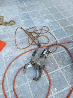
Cut the feeder
Once the phases have been identified, they can be safely cut using the shears, in this case all three phases at once with a single cut.
Phase identification at junction


At the junction point, there are 6 terminals, three from the source SS and the other three from the final SS. They are identified and marked. Having a Merytronic PI-3 device with dual transmitters saves a lot of time in this identification operation.
In this case, since there is a second transmitter available, TR-B, it remains connected at the final SS, injecting with clamp 1 into the cable marked as 1, with clamp 2 into the cable marked as 2, etc.
Return to the junction point to identify the 6 terminals. Remember that having two transmitters, TR-A with three clamps injecting the signal from the source SS to the interconnection point, and TR-B with three clamps injecting the signal simultaneously from the final SS to the junction point.
The use of two transmitters with different encodings (A and B) optimises the process, allowing an Efficient, Accurate and Safe reconnection of the power line phases.
If you want to know more about our electrical safety solutions, click on the banner.
Related News

Procedure for Cutting and Reconnection of a Medium Voltage Power feeder
During maintenance work on medium-voltage electrical networks, it is common to cut and reconnect electrical...
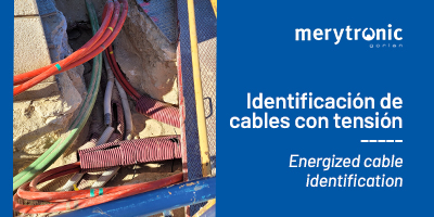
How to identify an energized cable safely?
Identify any type of cable with Ariadna CI In maintenance tasks, correctly identifying cables in...
Advantages of identifying live LV and MV electrical cables
Identification of live electrical cables, a need The repair of breakdowns and maintenance works on...
Dowloads
Access all the information about our products.

Merytronic, a ![]() company
company
- Electric network digitisation | Network topology
- Low Voltage distribution monitoring systems | Smart Grids
- Maintenance: electricity distribution networks
- Electrical Safety | Cable Identifier
- Maintenance: underground piping networks
- Piping networks digitisation for Oil&Gas
- Merytronic Training Center
- R&D projects
